|
|
|
WIRE ROPE
INSTALLATION, OPERATION AND
MAINTENANCE RECOMMENDATIONS
As a rope is run through a groove, both become smaller. A
used goove can be too small for a new rope; thus acceler
ating rope wear. A compromise between rope life and
machining frequency must be made.
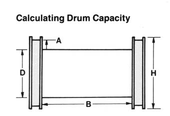
The lenth of rope that caan be wound on a drum or reel
may be calculated as follows. L= lenth of rope in feet. All
other dimensions are in inches.
L = (A + D) x A x B x K
K=Constant obtained by dividing .2618 by the square of
Grooves should have an arc of contact with the wire rope
the actual rope diameter.
between 135 and 150 degrees. They should be tapered to
permit the rope to enter and leave the groove smoothly.
A = H D Desired clearance, in inches.
Field inspection groove guages are made to the nominal
2
diameter of the rope plus 1/2 of the allowable rope oversize
tolerance. When the field inspection guage fits perfectly,
B = Traverse in inches.
the groove is at the minimum permissible contour.
D = Barrel Diameter in inches.
H = Flange Diameter in inches.
L = Rope length in feet.
Values of K
Rope
Rope
K
K
Dia.
Dia.
1/4"
3.29
1 1/2"
0.107
5/16"
2.21
1 5/8"
0.0886
3/8"
1.58
1 3/4"
0.077
7/16"
1.19
1 7/8"
0.0675
1/2"
0.925
2"
0.0597
9/16"
0.741
2 1/8"
0.0532
5/8"
0.607
2 1/4"
0.0476
3/4"
0.428
2 3/8"
0.0421
7/8"
0.308
2 1/2"
0.038
1"
0.239
2 5/8"
0.0345
1 1/8"
0.191
2 3/4"
0.0314
1 1/4"
0.152
2 7/8"
0.0287
1 3/8"
0.127
3"
0.0264
18